<< Read Previous Part 1 >> Read Next Part 3
In the Part 1 of this series we talked about the required parts to build a low cost, green, $400 Windows Home Server based on the Shuttle KPC. In Part 2 we will show you step-by-step how it all comes together.
- Here is a list of everything we will be using.
- Shuttle KPC
- Intel Pentium E2160 1.8GHz Dual Core
- WD 500GB hard drive
- Kingston 512MB Memory

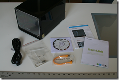
- Here's what you will find when you unbox the Shuttle KPC box.
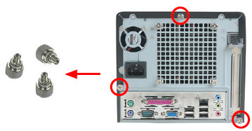
- Unscrew the 3 tool-less thumbscrews on the back of the KPC.
- Remove the cover by sliding the cover back on the case and then upwards.

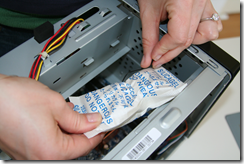
- Remove and discard the silica packet that is twist tied in the drive bay.
- Please take a moment to familiarize yourself with the KPC motherboard and the connectors that we will be using in this project.

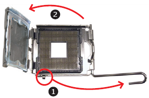
- Before removing CPU from box, prepare the socket. First unlock and raise the socket lever, then lift the metal load plate on the CPU socket.
- Move the power supply cords out of the main cavity, out of your way.
- Carefully remove CPU from box, holding at the edges. DO NOT TOUCH THE METAL TOP OF THE PROCESSOR. From now until you install it, only hold the CPU from edges. It is important that you don't get any oils from your fingers on this surface.
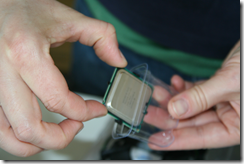
- Carefully remove and discard the black plastic protective cover from the bottom surface.
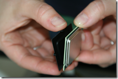
- Now that the pads are exposed, DO NOT TOUCH THE BOTTOM SURFACE. Just hold from edges and your processor will be clean and happy. Don't you want that?
- Set the fan aside. DO NOT TOUCH THE BOTTOM OF THE FAN, the part with the gray gooey stuff. (Eventually, the top of the processor and the bottom of the fan will be touching each other and we don't want any finger residue on either side.)
- Now is the time where barebone PC purists will tell you to clean and remove the factory fan goo in preparation for using a quality thermal paste like Arctic Silver 5 Thermal Compound. As much of a purist as I tend to be, even in this case, as this is a low power processor and hobbyist project, we didn't feel it was necessary. But feel free to do so if you know what you are doing.
- Install CPU - You can approach either from the top or side opening. Unlike other processors, this one has no pins, just pads. Therefore, it is easier to drop in because there is less risk of severely maiming it. Now, orient the CPU with the socket, aligning the yellow triangle on the corner of the CPU with the notched corner of the socket (closest to the copper colored heat sink). Carefully lower into place.
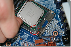
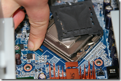
- Close the load plate (step 1 in figure below). It just lowers and lays flat, no snapping into place. Lower the CPU socket lever (step 2 in figure below). There WILL be some resistance as you push down (it is NOT futile) and then lock in place. There is a chance that the black plastic cover on the load plate will pop off as you are closing the lever. As you can see in the photo, this happened to us as we were installing. The next step is to remove it anyway, so it's ok.
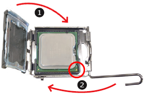
- If it didn't pop off in the last step, remove the protective socket cover (again being sure not to touch the top of the processor) and discard or, as this is a green PC, recycle.
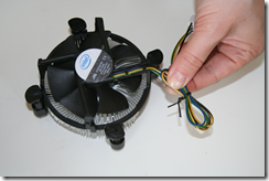
- Prepare fan for installation. First, the wire for the fan included with the processor is very long and is wrapped around the edge of the fan and fitted into two little clamps. There is a risk of the wires getting caught in the fan, so we prefer to remove the wire from the two clamps and bundle it. Luckily, we have a twist tie from removing the silica packet, so we just used that and trimmed the excess. Otherwise, you could use one of the small zip strips that come in the plastic bag of goodies included with the shuttle.

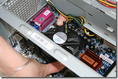
- Install fan. Notice that the 4 pins at the corners of the fan pop in to the 4 mounting holes. Also notice that the fan connector plugs in to the motherboard where it is marked "FAN 1" (see photo in step 6). So, orient the fan so as to minimize the cord distance between the connector and plug. Now go ahead and rest the pins in the holes and make sure they are really lined up.
- Approaching from either side, use both thumbs at once to press down on the two pins at opposite corners. Then press in the other two pins at the same time.
- Troubleshooting note - First, we tried pressing one pin at a time and it ruined the alignment enough that we just couldn't press in the final pin. This glitch taught us 1) that two at a time is better and 2) how to undo the pins if you need to start from scratch. Notice the arrows embossed on the black plastic top of the pins. We used a small screwdriver to unscrew the pin in the direction of the arrow, which allowed it to pop back out. Turn the pins 90% back to the original position before trying again.
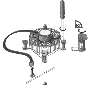
- Plug in the fan connector. There isn't a lot of room inside this computer (which we like because that makes it nice and small) so it can be hard to see what you are doing. For this step, it is easiest to reach in through the top opening while looking in through the power supply side opening. This gives the best view of the prongs and made it easy to line them up.
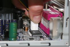
- Next we will install the memory. If you are installing a single 512KB stick, you must place it in the slot marked DIMM1 (which will be towards the rear of the computer). If you are installing 2 sticks of 1GB memory, you will place one stick into DIMM1 and one stick into DIMM2. The ejection levers (white in the picture below) should be facing out when you get the motherboard (if not, flip them outwards) and they will automatically close around the memory when you snap it in. The memory is keyed so that it will go in only one way. It should make a "snap" noise if it is properly seated.
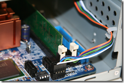
- Now its time to install the hard drive. We will be installing only one drive right now. The other optional drive will be installed after we have the system fully operational.
- Take the drive that you would like to use as a system drive and place it in the lower drive bay. Secure it to the chassis with 4 screws (2 on each side). Note that it's really not necessary to secure the drive on both sides but doing so will cut down on vibration and thus noise level.
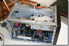
- Attach the L-shaped end of the orange SATA data cable (that came with the KPC) to the back of the drive. It should snap into place as it has a retaining clip.
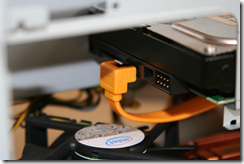
- Attach the other end of the SATA data cable to the motherboard in the connector marked SATA1. Again it will snap into place.
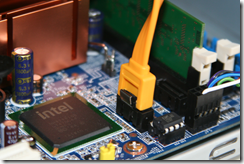
- Be sure that the cable has enough clearance to stay away from the spinning CPU fan.
- Plug in the power cord and attach it to the back your KPC.
You have just completed the basic barebones computer! As we don't have any boot devices, nothing will happen yet. You are now ready for Part 3, where we install WHS onto our newly assembled computer.


2 comments:
Very Nice article. I was thinking about just such a system but wanted to ensure the WHS would run fine. Thanks!!
Oh yeah, and thermal compund is VERY IMPORTANT so I have learned!!!!
~Jason Suarez
www.jason27.com
Very useful and nicely illustrated.
Thanks!
Dan
Post a Comment